RECTIFIERS - ACCUMULATOR CHARGERS AND DISCHARGERS
FOR INDUSTRIAL APPLICATIONS - OVERVIEW
GENERAL:
CONSTRUCTION:
 |
 |
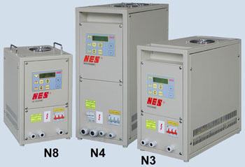
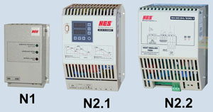 |
|
APPLICATION:
- Type M.1, M.5 - charging of stationary batteries (characteristics Uo, IUo, IUUo, IUIUUo)
- Type M.3 - charging / compensating charging of starting and traction batteries (IUIa, IUIIa)
- Type M.2 - universal chargers for charging stationary and traction batteries (Uo, IUo, IUUo, IUIUUo, IUIa, IUIaP, types without M.2 in tag - only characteristics Uo)
- Charging and simultaneous load / appliance feeding (types M.1, M.2, M.5, M.2-19)
- Battery charging for general application
| Block diagram of charger: | Output - type M.1: | Output - type M.2, M.5: |
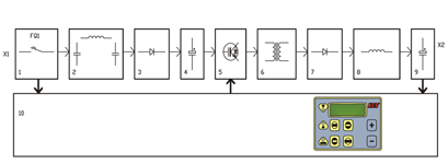 |
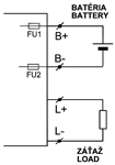 |
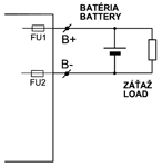 |
Block description: 1. input circuit breaker, 2. input filter, 3. input rectifier, 4.voltage inter-circuit, 5. inverter unit, 6. power transformer, 7. output rectifier, 8. output filter, 9. output filter, 10. power supply control and communication (types M.X only)
- Chargers functionality by power failure. Control unit is supplied in case of power failure from connected accumulators, i.e. all the accessible charger functions stay monitored, while the battery voltage does not drop on 50% Unom.
- Connection in parallel-redundant version. Individual devices communicate with each other and thereby are optimized operating parameters.
Chargers principle - type M.1:
Charger function - type M.2, M.5:
- to charge the batteries and to feed simultaneous the load
- to charge the batteries
- to feed the load
Charger function - type M.3:
| Technical parameters - general | |
|---|---|
| High switching frequency is reached due to used IGBT technology | |
| Output voltage rippling, stabilization | <= ±1% |
| Efficiency min. | 90% |
| Output voltage adjustment range | from 45 to 145% from nominal value - type M.X only |
| Output current adjustment range | from 1 to 100% from nominal value - type M.X only |
| Insulation strength input-output | 4 kVac, galvanically isolated |
| Covering | IP 20 |
| Cooling | own air, with forced air flow - standard for type M.X |
| with natural - no letter M in tag | |
TECHNICAL PARAMETERS
| Rectifier - charger type | Output | Input | Box type (dimensions - see page 3) |
Weight approx. [kg] / box type |
X - option | |||||||||
|---|---|---|---|---|---|---|---|---|---|---|---|---|---|---|
| Nominal voltage of battery |
Number of cells | Power [kW] |
Nominal current [A] |
Nominal voltage | M.1 | M.2 | M.3 | M.5 | M.2-19 | M.1-19 M.5-19 |
||||
| Pb | NiCd | |||||||||||||
| SN 10 24/230 B12 | 12V DC* | 6* | 10* | 0,15 | 10 | 1NPE 230V ±10%, TN-S, 50-60Hz |
N1 | 2 | ||||||
| SN 20 24/230.1 B12 | 12V DC* | 6* | 10* | 0,3 | 20 | N2.2 | 6 | |||||||
| SN 20 12/230MST | 12-16V DC | 6-8 | - | 0,32 | 20 | N2.1 | 6 | |||||||
| SN 20 24/230.1 A30 B12 | 12V DC* | 6* | 10* | 0,45 | 30 | N2.2 | 6 | |||||||
| SN 10 24/230 A5 | 24V DC* | 12* | 20* | 0,15 | 5 | 1NPE 230V ±10%, TN-S, 50-60Hz |
N1 | 1,8 | ||||||
| SN 10 24/230 | 24V DC* | 12* | 20* | 0,3 | 10 | N1 | 2 | |||||||
| SN 20 24/230.1 | 24V DC* | 12* | 20* | 0,56 | 20 | N2.2 | 6 | |||||||
| SN 20 24/230MST | 20-24V DC | 10-12 | - | 0,62 | 20 | N2.1 | 6,5 | |||||||
| SN 25 24/230X | 12-24V DC | 6-13 | 9-20 | 0,78 | 25 | N3 -M.1,M.5 / N8 -M.2,M.3 | 20 | X | X | X | X | |||
| SN 35 24/230X | 12-24V DC | 6-13 | 9-20 | 1,1 | 35 | N3 | 30 | X | X | |||||
| SN 40 24/230X | 12-24V DC | 6-13 | 9-20 | 1,25 | 40 | N3 | 30 | X | X | |||||
| SN 50 24/230X | 12-24V DC | 6-13 | 9-20 | 1,56 | 50 | N3 -M.1,M.2,M.3,M.5 / N19.4 -M.2-19 |
35-N3 / 19-N19.4 |
X | X | X | X | X | ||
| SN 50 24/400X | 12-24V DC | 6-13 | 9-20 | 1,56 | 50 | 3NPE 400V AC ±10%, 50-60Hz, TN-S |
N4 -M.1,M.5 / N3 -M.2,M.3 / N19.4 -M.2-19 |
35-N3 / 40-N4 / 19-N19.4 |
X | X | X | X | X | |
| SN 100 24/400X | 12-24V DC | 6-13 | 9-20 | 3,12 | 100 | N4 -M.1,M.5 / N3 -M.2,M.3 / N19.6-M.1,M.5 |
36-N3 / 45-N4 / 25-N19.4 |
X | X | X | X | X | ||
| SN 150 24/400X | 12-24V DC | 6-13 | 9-20 | 4,68 | 150 | N4-M.1,M.2,M.3,M.5 / N19.6-M.1-19,M.5-19 |
50-N4 / 35-N19.6 | X | X | X | X | X | ||
| SN 200 24/400X | 12-24V DC | 6-13 | 9-20 | 6,24 | 200 | N5-M.1,M.2,M.3,M.5 / N19.6-M.1-19,M.5-19 |
58-N5 / 39-N19.6 | X | X | X | ||||
| SN 10 48/230 | 48V DC* | 24* | 40* | 0,56 | 10 | 1NPE 230V ±10%, TN-S, 50-60Hz |
N2.2 | 6 | ||||||
| SN 20 48/230X | 24-48V DC | 12-26 | 18-40 | 1,25 | 20 | N8-M.2,M.3 | 25 | X | X | |||||
| SN 20 48/400X | 24-48V DC | 12-26 | 18-40 | 1,25 | 20 | 3NPE 400V AC ±10%, 50-60Hz, TN-S |
N3-M.2,M.3 / N19.4 -M.2-19 |
33-N3 / 23-N19.4 | X | X | X | |||
| SN 25 48/400X | 24-48V DC | 12-26 | 18-40 | 1,56 | 25 | N4 -M.1,M.5 / N3 -M.2,M.3 / N19.4 -M.2-19 |
35-N3 / 23-N19.4 | X | X | X | ||||
| SN 50 48/400X | 24-48V DC | 12-26 | 18-40 | 3,12 | 50 | N4 -M.1,M.5 / N3 -M.2,M.3 / N19.4 -M.2-19 |
35-N3 / 40-N4 / 24-N19.4 |
X | X | X | X | X | ||
| SN 100 48/400X | 24-48V DC | 12-26 | 18-40 | 6,24 | 100 | N4-M.1,M.2,M.3,M.5 / N19.6-M.1-19,M.5-19 |
50-N4 / 35-N19.6 | X | X | X | X | X | ||
| SN 150 48/400X | 24-48V DC | 12-26 | 18-40 | 9,36 | 150 | N5 | 55 | X | X | X | X | |||
| SN 300 48/400X | 24-48V DC | 12-26 | 18-40 | 18,7 | 300 | N5.4 | 90 | X | X | X | X | |||
| SN 8 60/230 | 60V DC* | 30* | 50* | 0,56 | 8 | 1NPE 230V ±10%, TN-S, 50-60Hz |
N2.2 | 6 | ||||||
| SN 10 60/230X | 30-60V DC | 15-32 | 22-50 | 0,78 | 10 | N8 | 20 | X | X | |||||
| SN 25 60/400X | 30-60V DC | 15-32 | 22-50 | 1,95 | 25 | 3NPE 400V AC ±10%, 50-60Hz, TN-S |
N4 -M.1,M.5 / N3 -M.2,M.3 / N19.4 -M.2-19 |
35-N3 / 40-N4 / 24-N19.4 |
X | X | X | X | X | |
| SN 50 60/400X | 30-60V DC | 15-32 | 22-50 | 3,9 | 50 | N4-M.1,M.2,M.3,M.5 / N19.6-M.1-19,M.5-19 |
50-N4 / 35-N19.6 | X | X | X | X | X | ||
| SN 100 60/400X | 30-60V DC | 15-32 | 22-50 | 7,8 | 100 | N5 | 60 | X | X | X | X | |||
| SN 150 60/400X | 30-60V DC | 15-32 | 22-50 | 11,7 | 150 | N5 | 65 | X | X | X | X | |||
| SN 25 80/400X | 40-80V DC | 20-44 | 30-67 | 2,6 | 25 | 3NPE 400V AC ±10%, 50-60Hz, TN-S |
N3 | 35 | X | X | ||||
| SN 60 80/400X | 40-80V DC | 20-44 | 30-67 | 6,24 | 60 | N4 | 50 | X | X | |||||
| SN 100 80/400X | 40-80V DC | 20-44 | 30-67 | 10,4 | 100 | N5 | 60 | X | X | |||||
| SN 150 80/400X | 40-80V DC | 20-44 | 30-67 | 15,6 | 150 | N5.4 | 90 | X | X | |||||
| SN 4 110/230 | 110V DC* | 56* | 86* | 0,57 | 4 | 1NPE 230V, TN-S, 50Hz |
N2.2 | 6 | ||||||
| SN 10 110/400X | 54-110V DC | 27-56 | 40-86 | 1,43 | 10 | 3NPE 400V AC ±10%, 50-60Hz, TN-S |
N3 -M.2 / N19.4 -M.2-19 | 35-N3 / 24-N19.4 | X | X | ||||
| SN 20 110/400X | 54-110V DC | 27-56 | 40-86 | 2,86 | 20 | N4 -M.1,M.5 / N3 -M.2 / N19.4 -M.2-19 |
35-N3 / 40-N4 / 24-N19.4 |
X | X | X | X | |||
| SN 40 110/400X | 54-110V DC | 27-56 | 40-86 | 5,7 | 40 | N4-M.1,M.2,M.3,M.5 / N19.6-M.1-19,M.5-19 |
50-N4 / 35-N19.6 | X | X | X | X | |||
| SN 50 110/400X | 54-110V DC | 27-56 | 40-86 | 7,15 | 50 | N4-M.1,M.2,M.3,M.5 / N19.6-M.1-19,M.5-19 |
50-N4 / 35-N19.6 | X | X | X | X | |||
| SN 100 110/400X | 54-110V DC | 27-56 | 40-86 | 14,3 | 100 | N5 | 65 | X | X | X | ||||
| SN 150 110/400X | 54-110V DC | 27-56 | 40-86 | 21,5 | 150 | N6.4 | 95 | X | X | X | ||||
| SN 200 110/400X | 54-110V DC | 27-56 | 40-86 | 28,6 | 200 | N6.4 | 120 | X | X | X | ||||
| SN 250 110/400X | 54-110V DC | 27-56 | 40-86 | 35,7 | 250 | N6.4 | 140 | X | X | |||||
| SN 2 220/230 | 220V DC* | 110* | 170* | 0,57 | 2 | 1NPE 230V, TN-S, 50Hz |
N2.2 | 6 | ||||||
| SN 10 220/400X | 108-220V DC | 54-110 | 80-170 | 2,86 | 10 | 3NPE 400V AC ±10%, 50-60Hz, TN-S |
N4-M.1,M.5 / N3-M.2 / N19.4-M.2-19 |
35-N3 / 40-N4 / 23-N19.4 |
X | X | X | X | ||
| SN 20 220/400X | 108-220V DC | 54-110 | 80-170 | 5,7 | 20 | N4-M.1,M.2,M.3,M.5 / N19.6-M.1-19,M.5-19 |
50-N4 / 35-N19.6 | X | X | X | X | |||
| SN 25 220/400X | 108-220V DC | 54-110 | 80-170 | 7,1 | 25 | N4-M.1,M.2,M.3,M.5 / N19.6-M.1-19,M.5-19 |
50-N4 / 35-N19.6 | X | X | X | X | |||
| SN 50 220/400X | 108-220V DC | 54-110 | 80-170 | 14,3 | 50 | N5 | 60 | X | X | X | ||||
| SN 100 220/400X | 108-220V DC | 54-110 | 80-170 | 28,6 | 100 | N5.4 | 110 | X | X | |||||
| SN 150 220/400X | 108-220V DC | 54-110 | 80-170 | 42,9 | 150 | N6.4 | 150 | X | X | |||||
| SN 200 220/400X | 108-220V DC | 54-110 | 80-170 | 57,2 | 200 | w-1000 x h-1800 x h-450 mm | 180 | X | X | |||||
| SN 240 220/400X | 108-220V DC | 54-110 | 80-170 | 62,4 | 240 | w-1000 x h-1800 x h-450 mm | 195 | X | X | |||||
Min./ max. voltage per cell at charging or maintaining for X - extended equipment: 2 to 2,8V/cell Pb, 1 to 1,8V/cell NiCd, for the type MST 2,2 to 2,6V/cell
* Fixed values of voltage are set, changeable only in some range and only manufacturer NES can change them
* Fixed values of voltage are set, changeable only in some range and only manufacturer NES can change them
| Standard equipment | ||
|---|---|---|
| Control unit | microprocessor control system - type M.X only | |
| without microprocessor - no letter M in tag | ||
| Required current and voltage entering | from charger keyboard, evaluated on LCD display - type M.X only | |
| Device state and error signalling | LED - running, charging, overheating, LCD type M.X only | |
| Programming/adjusting of battery type | NiCd or Pb - type M.X only | |
| Programmed error signalling with one relay - type M.2, M.3, three relay - type M.1, M.5 (voltage-free contacts) | requires stopping the charging | 1. error - overheating |
| 2. error - internal charger error | ||
| 3. error - output voltage loss (shutdown from keyboard) | ||
| 4. error - input voltage loss (supply) - type M.1, M.5 only | ||
| does not require stopping of charging | 5. error - discharged battery (RE1) | |
| 6. error - temperature sensor error | ||
| 7. error - short-circuit - type M.1, M.5 only | ||
| 8. error - battery circuit opening - type M.1, M.5 only | ||
| On the panel of SN 10 24/230 charger are located 3 LED diodes that signal the operating states of charger - charging mode, keeping mode and error. | ||
| On the panel of SN 20 24/230MST charger is located a keyboard by that programs charging parameters and displays operating states of charger on 2x3 digits LED display. On the terminal block is running out the programmable voltage-free contact for error message, clamps for temperature sensor, clamps pre load connection and clamps for battery connection. | ||
| Others chargers with output error from 0,29kW to 0,57kW have 2 LED diodes that signal operating states of charger. Voltage-free contact for error message is running out on the terminal block. | ||
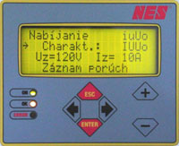
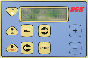
Standard control panel of chargers - type M.X:
OPTIONS - CHARGER ACCESSORIES
MONITORING AND COMMUNICATION ACCESSORIES
ANALOG VOLTAGE REGULATOR
BATTERY DISCONNECTOR
For chargers with output power to 570W is battery disconnector solved like a separate external module, for chargers with output power over 570W is battery disconnector built-in into charger box.
INSULATION RESISTANCE METERS
CONTROL PANEL WITH BIG LCD FOR CHARGERS TYPE M.1 AND M.5
ANALOG SIGNALS - OUTPUTS
STANDS FOR CHARGERS
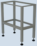
| Type | Dimensions W x H x D (mm) | Charger box type |
|---|---|---|
| Stojan N8 | 270 x 500 x 315 | N8 |
| Stojan N3 | 270 x 500 x 495 | N3 |
| Stojan N4 | 265 x 500 x 510 | N4 |
| Stojan N5 | 610 x 760 x 360 | N5 |
| Stojan N3.1 | 270 x 250 x 495 | N3.1 |
| Stojan N4.1 | 265 x 300 x 510 | N4.1 |
TEMPERATURE PROBE
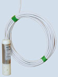
| Type | Description, parameters | |
|---|---|---|
| TSV100 | temperature | -40° až +60°C |
| output | 0-20mA | |
REMOTE CONTROL AND MONITORING OF TRACTION CHARGERS
BOX DIMENSIONS
| Charger box type | Dimensions W x H x D (mm) |
|---|---|
| N1 | 135 x 190 x 100 |
| N2.1 | 185 x 260 x 175 |
| N2.2 | 170 x 240 x 180 |
| N8 | 260 x 440 x 300 |
| N3 | 260 x 490 x 480 |
| N4 | 255 x 620 x 500 |
| N5.1 | 600 x 800 x 350 |
| N5.4 | 606 x 1800 x 45 |
| N6.4 | 806 x 1800 x 450 |
| N19.4 | 19“(480) x 4HU(177) x 430 |
| N19.6 | 19“(480) x 6HU(265) x 450 |
| Ambient conditions according to IEC 60 364-3 (STN 33 2000-3) | |
|---|---|
| Ambient temperature | AB4 ( from -5 °C to + 40 °C ) |
| Altitude | AC1 ( to 2000 m above sea level ) |
| Water occurrence | AD1 ( insignificant ) |
| Occurrence of foreign matters | AE1 ( insignificant ) |
| Occurrence of corrodents or pollutants | AF1 ( insignificant ) |
| Vibrations | AH2 ( middle ) |
| EMC | STN EN 50081-1: 1998 |
| STN EN 50082-2: 1999 | |
| Storage temperature range | from -25 to +40°C, no longer than 24 h to +70°C |
ACCUMULATOR DISCHARGERS
RELATED PRODUCTS
- DEVICES FOR AUTOMATED ACCUMULATOR CHARGING AND ACCUMULATOR CAPACITY TESTING
- CHARGER / DISCHARGER - ACCUMULATOR TESTER
- SOFTWARE FOR CHARGERS, REMOTE CONTROL
- SERVICE CHARGERS AND DISCHARGERS
- UPS FOR EMERGENCY LIGHTNING
- BACK-UP POWER SUPPLIES - AC/DC, DC/DC, DC/AC
 |
DEHOR-elspec Litvínov s.r.o. Jiráskova 413 436 01 Litvínov Czech Republic (CZ) web: http://www.dehor.cz e-mail: dehor@dehor.cz |
